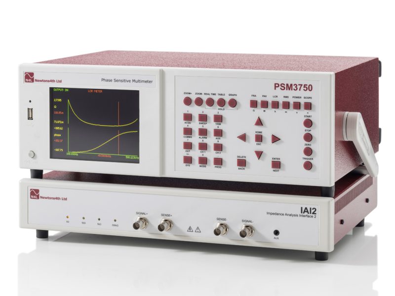
Using an impedance analyzer is a great way to determine the amplitude, frequency, and phase of an electrical impedance. These are important measurements for a variety of applications. The information obtained from an impedance analyzer can be used to design a system, perform a diagnostic test, or determine the source of a problem.
Body impedance
Generally, body impedance is a measurement of the resistance of tissues to the flow of an electrical signal. Bioelectrical impedance analysis is one of the most popular methods used in clinical practice to evaluate clinical conditions and assess body composition. Bioimpedance measurements are also used to determine the prognosis of patients with certain diseases.
Bioimpedance analysis is a non-invasive method that measures resistance of various body tissues to an electrical signal. The measure is combined with other anthropometric data, such as height, age, weight, gender and ethnicity, to provide a more accurate body composition estimate. Several types of bioimpedance analyzers are used for this purpose. These include single-frequency bioimpedance (SF-BIA) and multi-frequency (MF-BIA) bioimpedance analyzers.
SF-BIA measures the resistance of different tissues at different frequencies. The inverse proportion of the assessed impedance and TBW (thigh-bone weight) is used as a measure of body composition. The measurement method is based on a single frequency.
MF-BIA uses four contact electrodes to measure the impedance of different body segments. The measured value of impedance is related to the length and height of the conductor.
Bioelectrical impedance analysis
Using bioelectrical impedance analysis (BIA) to measure body composition is a non-invasive, safe, and low-cost method. In fact, it can be used to detect and evaluate clinical conditions. It is used to assess whole-body water content, muscle mass, and fat-free mass.
It is also used to detect fluid overload in patients with end-stage kidney disease. However, it cannot be generalized to patients of other ethnicities. There are different BIA devices, ranging from the simplest to the most sophisticated. Most instruments use a system with two or more frequencies, while others adopt a system with a single frequency.
BIA devices differ in the number of electrodes used, the frequency of excitation signal, and in the section of the body being measured. A common device uses four electrodes. The most advanced device is the Direct Segmental Multi-Frequency BIA.
Bioelectrical impedance analysis detects the total body water content, which accounts for 45 to 60 percent of the total body weight. This is measured in high frequencies, which can be seen in a graphic display.
Precision impedance analyzers
Typically, impedance analyzers are used to characterize electronic circuits, dielectric materials and other components. Precision impedance analyzers are designed to perform highly accurate measurements. They feature a wide range of frequencies, from a few Hz to several MHz. In addition, they can provide current and phase angle measurement.
These devices are suitable for a wide variety of applications. They are especially good for evaluating the performance of passive components, such as capacitors. They have easy graphical interfaces, high resolution color displays, and thorough testing. They are perfect for circuit designers and manufacturers of passive components.
Precision Impedance Analyzers measure Impedance (Z), Capacitance (C), Reactance (G), Phase Angle (P) and Susceptance (B). The basic accuracy of these instruments is between 0.05% and 0.05%.
A number of models are available in a wide variety of price ranges. Some of the higher priced models have a wide range of frequencies. They can test at a high frequency of 120 MHz.
Reactance chart
Typical impedance analyzers come with a reaction chart, which provides an accurate representation of the impedance for a given frequency. These charts are also referred to as accuracy charts. They are used in a variety of applications, including characterizing the dielectric material used in components.
Reactance charts provide an easy way to visualize the impedance of an electronic circuit with a specified frequency. Inductive and capacitive reactance are shown in the upper half of the chart, while negative reactances are displayed in the lower half. An antenna impedance chart, for example, shows arcs.
Another advantage of a hand-drawn chart is that it creates asymptotic plots that are more intuitive and understandable than those produced by numerical analysis tools. These plots also display the effect of a component’s values on the circuit.
One of the most useful types of reactance charts is the Smith chart. It was developed to address complicated math problems around transmission lines and matching circuits.

